

Why take this course
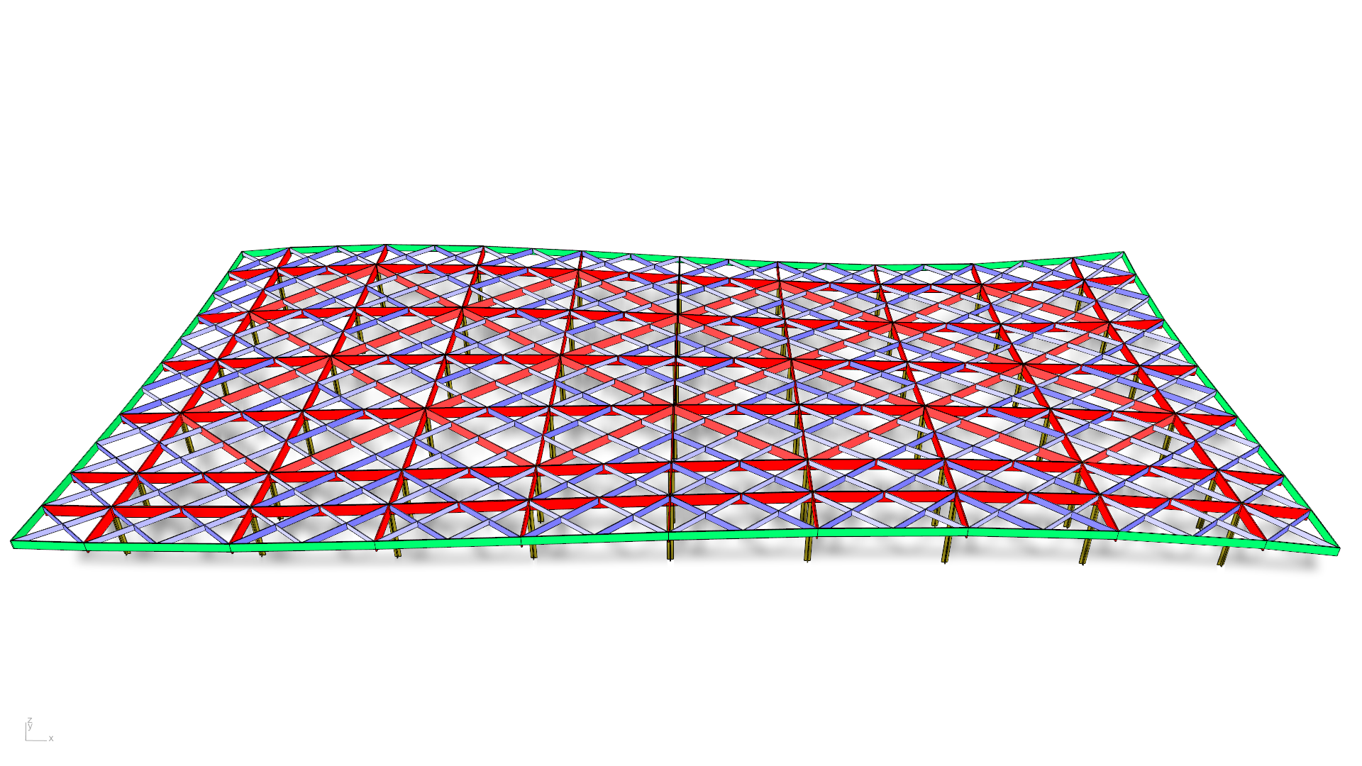
In the first part of this exercise, we built a complex flat structural grid. Now, we take that geometry to the next level by turning it into a fully realized 3D wave roof. This course uses the stunning Sydney Fish Market project to teach you advanced parametric workflows. You will learn how to turn basic linework into real structural members with accurate thickness.
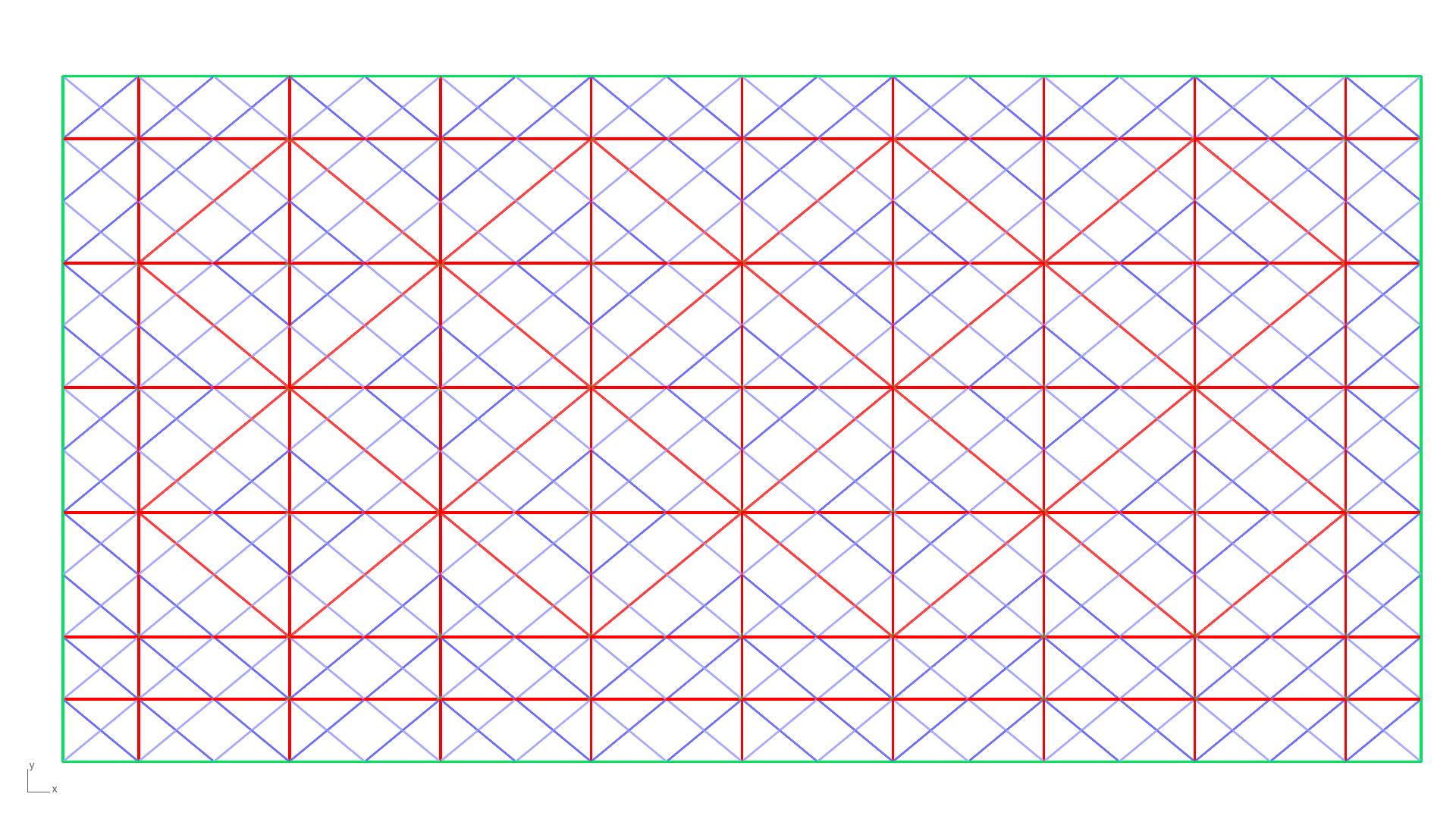
Coordinating a massive curved roof by hand is a total nightmare. This course shows you how to automate the hardest parts of architectural modeling. You will standardize every beam, resolve complex intersections, and prepare exact construction data. By the end, you will have a robust model that updates instantly and outputs precise manufacturing layouts.

What you will learn and why it matters
You will learn how to transform flat lines into a rationalized 3D structure ready for fabrication. We will cover advanced techniques for sorting data, projecting curved geometry, and generating automated text tags. This matters because it bridges the gap between a visual concept and a highly functional set of construction drawings.
Adding Beam Thickness
You will use the Clipper plugin to offset lines and create closed profile shapes. We will cover Boolean operations to automatically subtract overlapping segments at structural intersections. This process is highly valuable. It saves you from manually trimming hundreds of intersecting lines and prevents messy overlaps.
Accurate 3D Projection
Projecting grid points directly onto a double curved surface creates tiny visual gaps between elements. You will learn a step by step hierarchy to project main, secondary, and tertiary nodes precisely. This technique is absolutely essential. It ensures every single structural connection aligns flawlessly without any floating geometry.
Flat Layouts for Manufacturing
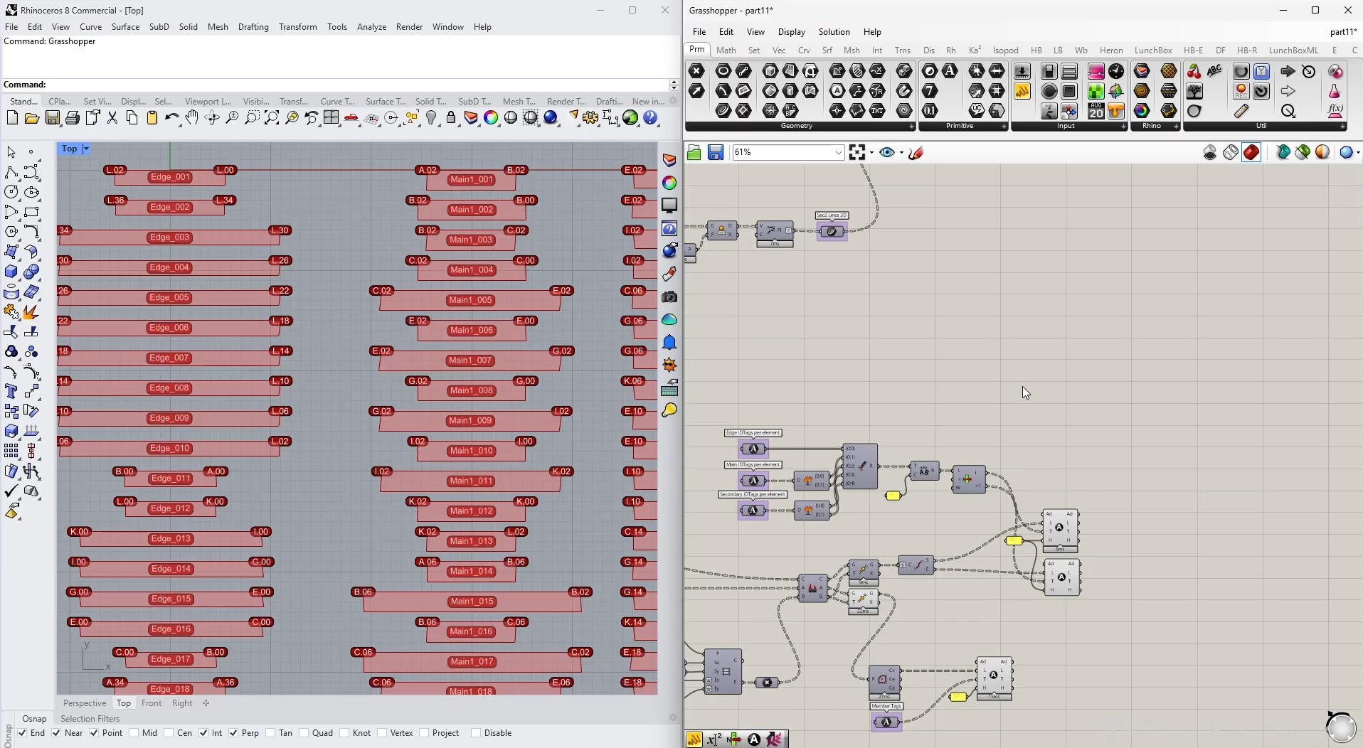
We will extract every 3D beam and orient it perfectly flat onto a standard coordinate plane. You will organize these flattened parts into a clean grid layout. This skill is critical for digital fabrication. It turns a complex 3D shape into physical components that a manufacturer can actually cut and build.
Smart Automated Tagging
You will extract node data to generate dynamic text tags for every individual beam in your model. We will label each member with its exact start and end connection points. This creates incredibly clear construction documents. It prevents massive confusion during assembly and keeps your data beautifully organized.
1.- Organizing the 2D Structural Grid
20min 41seg2.- Applying 2D Thickness with Clipper
13min 56seg3.- Trimming Lines for Structural Nodes
18min 37seg4.- Refining Edge & Corner Conditions
11min 00seg5.- Projecting Structural Lines to the 3D Surface
20min 45seg6.- Accuracy-Driven 3D Projection Logic
12min 55seg7.- Giving Thickness to the 3D Lines
17min 27seg8.- 3D Member Thickness & Fabrication Layout
20min 00seg9.- Parametric Tagging & Annotation Dots
17min 07seg10.- Node Organization & Numbering
20min 07seg11.- Generating Construction Data Sets
20min 39seg12.- Column Modeling & Rhino Baking Workflow
20min 13seg13.- Conclusion
01min 01seg